Perspective and Clipping Transforms
Sean Erik O'Connor
November 2009-October 2010
Introduction
This notebook displays wireframe models in perspective projection.
First, some simple conversion functions.
In[866]:=
![]()
In[867]:=
![]()
In[868]:=
![]()
Out[868]=
![]()
In[869]:=
![]()
In[870]:=
![]()
In[871]:=
![]()
Out[871]=
![]()
Euclidean and Homogeneous Coordinates
We'll use a left handed graphics coordinate system.
In[872]:=

Out[872]=
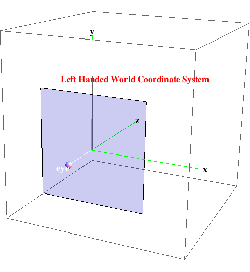
Convert between 3D Euclidean space and 4D homogeneous coordinates.
The 3D Euclidean point (x, y, z) transforms to (x, y, z, 1) in homogeneous coordinates.
In[873]:=
![]()
In[874]:=
![]()
Out[874]//MatrixForm=
![]()
The homogeneous point (x, y, z, w) transforms to (![]() ) in normalized homogeneous coordinates.
) in normalized homogeneous coordinates.
In[875]:=
![]()
In[876]:=
![]()
Out[876]//MatrixForm=
![]()
In[877]:=
![]()
In[878]:=
![]()
Out[878]=
![]()
Translation and Rotation
Develop the 4D homogeneous matrices for translations and rotations. We translate/rotate the coordinate system origin.
In[879]:=

Translate the origin by vector v = (1,2,3). (1,2,3) should now map to (0,0,0).
In[880]:=
![]()
In[881]:=
![]()
Out[881]//MatrixForm=

In[882]:=
![]()
Out[882]=
![]()
In[883]:=
![]()
Out[883]=
![]()
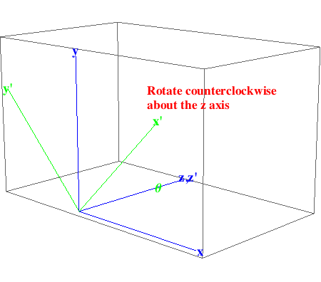
Rotate the origin by θ counterclockwise about the z axis.
In[884]:=

Out[884]=
In[885]:=

Rotate the origin by ![]() counterclockwise about the z axis. The point (
counterclockwise about the z axis. The point ( , 0) should map to (1,0,0).
In[886]:=
![]()
Out[886]//MatrixForm=
![]()
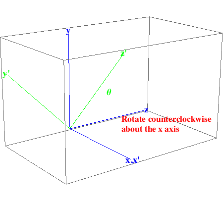
Rotate the origin by θ counterclockwise about the x axis.
In[887]:=

Out[887]=
In[888]:=

Rotate the origin by ![]() counterclockwise about the x axis. The point (
counterclockwise about the x axis. The point ( ) should map to (0,0,1) because
In[889]:=
![]()
Out[889]//MatrixForm=
![]()
Rotate the origin by ![]() counterclockwise about the x axis. The point (0,0,1) should map to (0,-1,0)
counterclockwise about the x axis. The point (0,0,1) should map to (0,-1,0)
In[890]:=
![]()
Out[890]//MatrixForm=
![]()
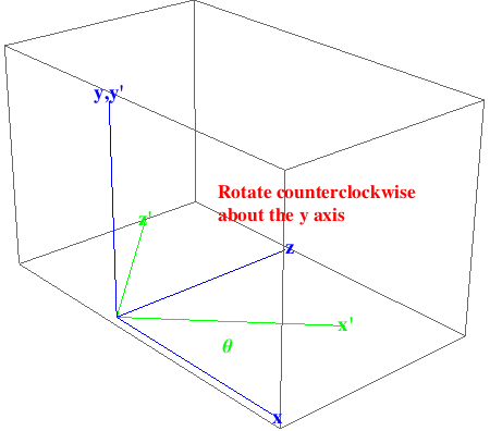
Rotate the origin by θ counterclockwise about the y axis.
In[891]:=

Out[891]=
In[892]:=

Rotate the origin by ![]() counterclockwise about the y axis. The point (
counterclockwise about the y axis. The point (![]() ) should map to (1,0,0).
) should map to (1,0,0).
In[893]:=
![]()
Out[893]//MatrixForm=
![]()
Perspective Projection
The perspective matrix lives in homogeneous coordinate space and maps the viewing frustrum to a unit parallelepiped for simplicity in clipping.
The eye is at the origin of the perspective view which forms a rectilinear cone.
The picture plane has width = wPP, height = hPP.
The distance from the eye to the picture plane is dPP and the distance from the eye to the far plane is dFP.
Try out translation and rotation.
In[894]:=
![]()
In[895]:=

In[896]:=
![]()
Out[896]//MatrixForm=

Helper function to project points (x,y,z) in 3D to (x,y) in 2D.
In[897]:=
![]()
In[898]:=
![]()
Out[898]=
![]()
Points on the near plane corners transform to normalized picture plane corners.
In[899]:=
![]()
Out[899]=
![]()
Point on the far plane corners transform to normalized picture plane corners.
In[900]:=
![]()
Out[900]=
![]()
General points (x,y,z) transform to
In[901]:=
![]()
Out[901]=
![]()
Points in normalized homogeneous perspective space project down the the 2D picture plane.
In[902]:=
![]()
In[903]:=
![]()
Out[903]=
![]()
2. Clipping
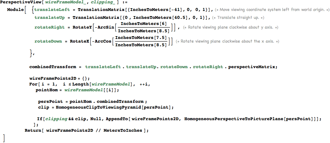
Clip a homogeneous point in perspective projection to the bounds of the viewing frustrum.
In[904]:=
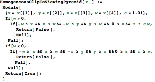
Test it out. Clipping should be false, then true for this example.
In[905]:=
![]()
Out[905]=
![]()
In[906]:=
![]()
Out[906]=
![]()
Wire Frame Components
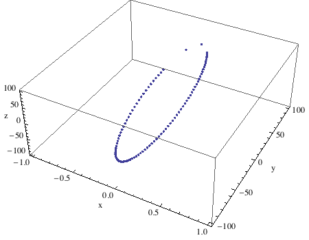
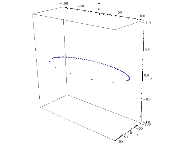
Circle in yz plane using left handed coordinate system, with variable spacing of points.
In[907]:=

Arrange the graph with +x to the right, +y upwards, and -z into the picture so we model a left handed viewing coordinate system.
In[908]:=
![]()
Out[908]=
In[909]:=

In[910]:=

Arrange the graph with +x to the right, +y upwards, and -z into the picture so we model a left handed viewing coordinate system.
In[911]:=
![]()
Out[911]=
Models and Views for a Real Table
In[912]:=

Calibrate by doing a simple view of a table top model.
Wire frame model of table top.
In[916]:=

Wire frame model of table top. Arrange the graph with +x to the right, +y upwards, and -z into the picture so we model a left handed viewing coordinate system.
In[917]:=
![]()
In[918]:=
![]()
Out[918]=
Perspective view.
In[919]:=
Quick test. Find a world coordinate point which maps to the center of the view.
In[920]:=
![]()
Out[920]=
![]()
Perpective view of the table.
In[921]:=

Out[921]=
Orbital Model and View
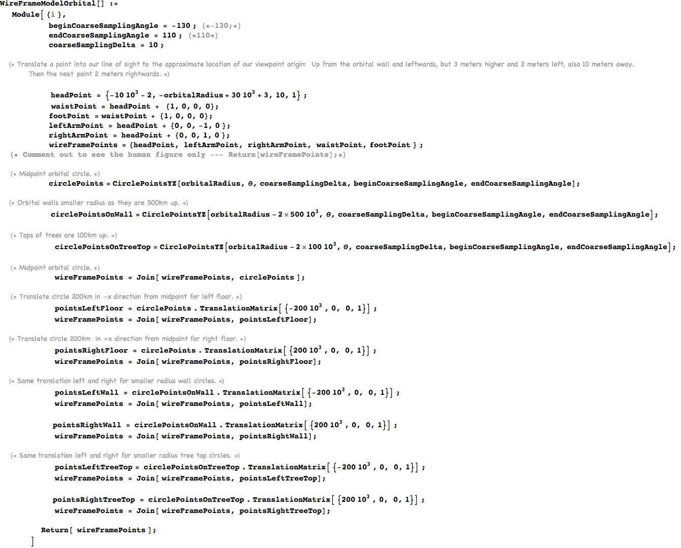
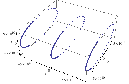
Our orbital!
In[922]:=
![]()
Angular spacing between points on the orbital circle having a radial distance of 100 km.
In[923]:=
![]()
Check gravity on the orbital.
In[924]:=

Out[925]=
![]()
Picture plane dimensions. Width and height are of my painting canvas. Distance to picture plane from eye seems reasonable.
In[926]:=

In[930]:=
Arrange the graph with +x to the right, +y upwards, and -z into the picture so we model a left handed viewing coordinate system.
In[931]:=
![]()
Out[931]=
In[932]:=
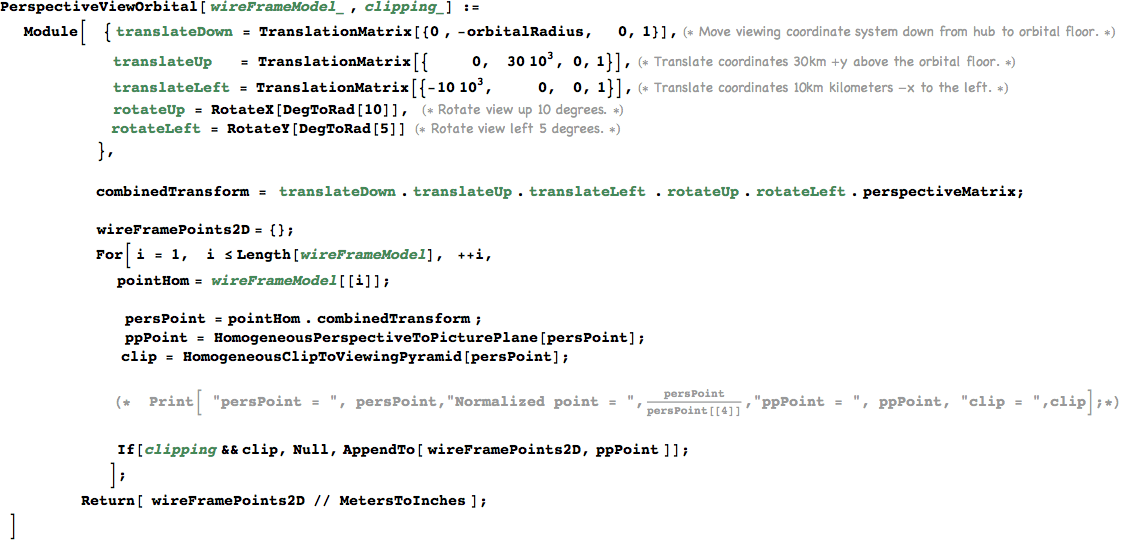
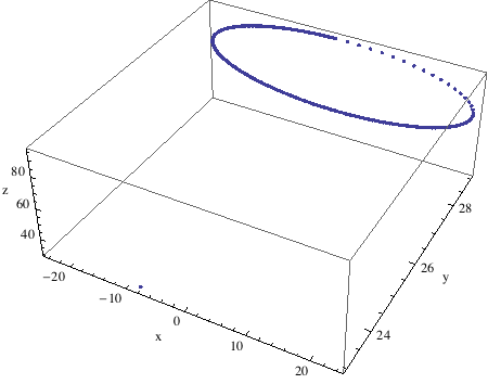
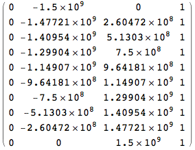
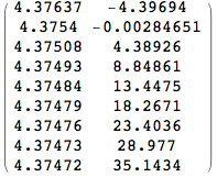
Plot a few points on the midpoint of the orbital circle to debug the perspectivc clipping.
In[933]:=
![]()
Out[934]//MatrixForm=
In[935]:=
![]()
Out[935]//MatrixForm=
In[936]:=

![]()
![]()
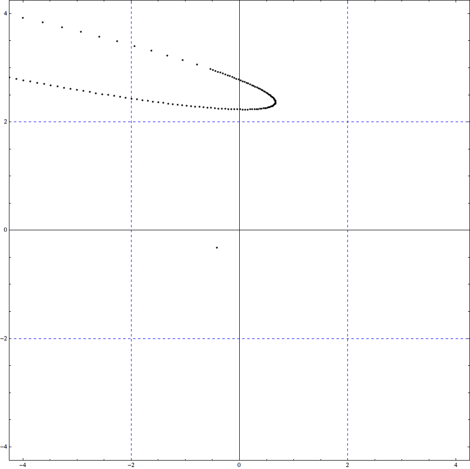
View the orbital in perspective from our chosen vantage point.
In[937]:=

Out[937]=
